


Save over ten thousand! This trick gives a 20-year-old imported die-cutting machine a brand new life!
In recent years, competition in the printing industry has intensified. To survive and develop in the fierce market competition, it is essential to create high-quality products while also reducing production costs. Besides raw materials and labor wages, production equipment also directly affects production costs. Therefore, it is necessary to retrofit production equipment with low investment to better meet production needs, especially for imported equipment with high maintenance costs. Facing high parts and technical service fees, if affordable and high-performance domestic parts can be used to replace and upgrade them, revitalizing equipment and continuing to create value for enterprise development and construction, this has become a consensus on controlling production costs.
Reasons for the renovation
Our company's inline roll paper flat-pressing die-cutting machine is produced by the Swiss company Boster. Since its introduction in 2002, it has played an important role in the company's production, performing indentation die-cutting processing on many products, and has been in use for a long time. The equipment has two discharge shafts; when one dispensing shaft dispenses, the other preloads the paper rolls. The braking torque of the discharge shaft is determined by the friction between the brake pad and the steel ring. The friction between the brake pad and the steel ring is achieved by six cylinders pushing the head. The magnitude of the pushing force is adjusted by the electric proportional air valve, which in turn restricts the output of the unwinding tension system control circuit board. The output signal from the tension control circuit board is linked to the potentiometer position signal on the tension floating roller, thus forming a complex closed-loop control system that combines pneumatic and electric elements.
During the use of this equipment, there have always been issues with unstable uncoiling tension causing downtime, frequent maintenance, and reduced production efficiency, while also increasing the defect rate. To address this fault, the brake pads, cylinders, electric proportional valve, potentiometer, and tension system control circuit board were replaced, but the issue was never fully resolved. Because these are imported equipment, spare parts often cost tens of thousands of yuan, and frequent faults affect product quality and production efficiency. Our company also frequently cleans and maintains brake pads, greatly increasing equipment maintenance costs.
Renovation ideas
To address this issue, our company considered installing a floating storage cabinet to increase the length of the paper circuit, using the floating cabinet to offset fluctuations in paper tension, and also considered replacing its brake system with a servo motor system to solve the problem. However, due to high renovation costs and many changes to be made, the project was not realized as expected. After careful consideration, we decided to replace it with an automatic constant tension magnetic particle brake system that is affordable, structurally simple, and stable in performance. The original pneumatic brake disc assembly and pneumatic control system were removed, magnetic powder brakes were installed on the two feeding shafts, and the feed shaft was driven by a synchronous belt. A paper tension sensor was installed on the paper guide roller at the front end of the original floating roller, and a Hall sensor was installed at the end of the middle paper guide roller to detect paper speed. The paper tension sensor detects the tension of the paper and feeds it back to the constant tension controller, which compares it with the tension value set by the constant tension controller. Based on the comparison, an analog value is fed to the magnetic powder brake, thereby controlling the controller's braking torque and meeting the closed-loop automatic constant tension control requirements.
Renovation achieved
Figure 1 is a schematic diagram of the equipment retrofit principle, where the paper tension sensor, Hall detection switch, synchronous belt, magnetic powder brake, constant tension controller, and synchronous pulley are the replacement and additional accessories. The specific details of each part in the schematic diagram are as follows:
(1) Post-press rolls are used to produce roll paper products;
(2) The paper feed path of the product is the paper path from the material discharge shaft to the workstation;
(3) The unwinding frame, paper guide roller, correction system, floating roller, and traction roller are the original equipment;
(4) Two paper tension sensors need to be installed, each under the bearing seats at both ends of the paper guide roller. The pressure generated by the paper on the paper guide roller detects the tension signal, and the voltage signals detected by the two sensors are transmitted via wires to the signal input terminal of the constant tension controller;
(5) The Hall detection switch is installed at either end of the paper guide roller, with a magnet attached to the end face of the guide paper roller. The paper drives the paper guide roller to rotate, and the Hall detection switch detects whether the magnet generates a pulse signal. This pulse signal is also transmitted via wire to the signal input of the constant tension controller;
(6) The synchronous belt is used to drive the pulley of the magnetic powder brake and the pulley of the discharge shaft;
(7) The braking torque of the magnetic powder brake can be selected. This time, a 400N torque parameter magnetic powder brake was selected according to the product tension requirements of the equipment. Since there are two feeding shafts, two magnetic powder brakes are needed. The braking torque signal is determined by the constant tension controller output via wires;
(8) The main function of the constant tension controller is to compare the tension set value with the sensor's set value, and through internal program calculation, obtain the final signal sent to the magnetic powder brake;
(9) The synchronous pulley needs to be added to the feeding shaft.
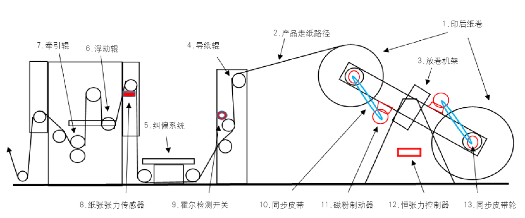
Figure 1 Schematic Diagram of Equipment Modification Principle
After this equipment modification was completed, the production performance over a year has been very good. Currently, the unwinding tension of the equipment is stable, operation is convenient, it has solved the problem of downtime caused by unstable tension, reduced the maintenance burden, and there's no more waste caused by tension issues during unwinding. Moreover, after the modification, the design is simple, performance is stable, and parts are inexpensive, achieving the goal of lowering production costs. Through this equipment modification, we hope our company will continue to do even better in the future with domestic replacements for imported equipment parts.