


Efficiency boosted by 129.67%! Quickly solve gravure press maintenance problems
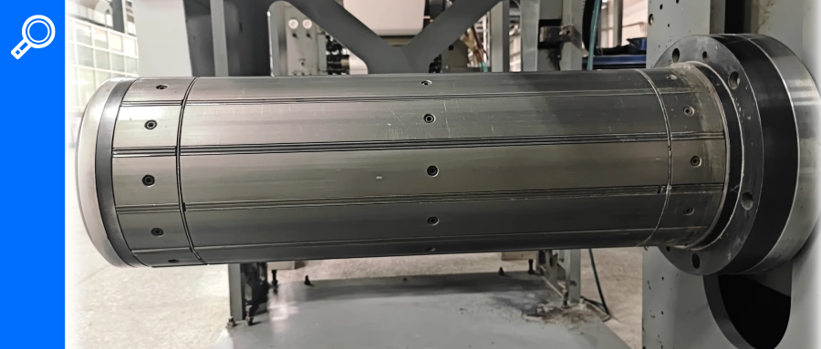
The company I work for has two 10-color gravure printing machines: one is an Italian Cerutti R960-3 10-color gravure press, and the other is a Zhongshan Songde SAY10820 10-color gravure press (as shown in Figure 1). They are mainly used to produce Seven Wolves cigarette packs. Both machines have a high effective operating rate, but when the air expansion strips in the unwinding shaft start leaking, the paper will shift side to side, causing misalignment during printing and resulting in a large amount of waste. Moreover, maintaining the air expansion shaft is time-consuming and labor-intensive.
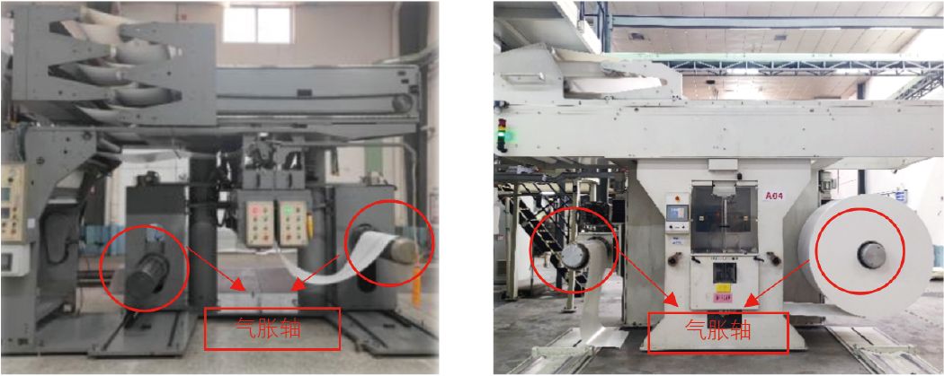 Figure 1: Unwinding mechanism of Zhongshan Songde SAY10820 gravure press (left) and Italy Cerutti R960-3 unwinding mechanism (right).
The author conducted an in-depth study on the maintenance issues of the air-expansion shaft. The results showed that during the installation and removal of the air-expansion shaft in the gravure press unwinding mechanism, due to the lack of specialized tools and the heavy weight of the shaft, multiple maintenance personnel are needed to coordinate using the base plate and a hydraulic forklift to support and pull out the shaft. Moreover, during installation, since the flange needs precise alignment before it can be inserted, maintenance staff often spend a lot of time controlling the position of the shaft, consuming a huge amount of manpower and resources, which goes against the company's goal of improving equipment effective operating rate. To solve this problem, our company decided to develop a device that can quickly install and remove the air-expansion shaft.
Current Maintenance Status
To further understand the current maintenance situation of the air-expansion shaft, technicians surveyed the average maintenance time from October to December 2020 and found that the average maintenance time was as high as 95.14 minutes. To avoid affecting production, machine operators need to slow down the machine to give the maintenance staff more time, and sometimes even after a full roll is printed, the shaft still isn't repaired, forcing the gravure press to stop. This not only affects production efficiency but also generates a lot of waste (assuming the maintenance time for the air-expansion shaft is T1, the time for the unwinding personnel to complete the A and B shaft splicing preparation is T2, and the minimum time for the machine to print a roll at the lowest speed is T3: if T1 + T2 < T3, the machine doesn't need to stop; if T1 + T2 > T3, the machine has to stop).
Challenges in Air-Expansion Shaft Maintenance
The air-expansion shaft is the part of the unwinding mechanism that holds the fixed paper rolls. By injecting compressed air, the expandable rubber strips on the shaft inflate, pushing up the expansion steel strips to secure the paper roll. This allows the roll to rotate synchronously with the shaft, enabling the unwinding mechanism to actively feed the roll. Technicians conducted a survey and analysis of air-expansion shaft maintenance and mapped out the process in a flowchart (Figure 2). Through in-depth investigation and analysis of the maintenance process, two main challenges were identified.
 Figure 2 Pneumatic Shaft Maintenance Flowchart
01/ Difficulty Installing the Pneumatic Shaft Flange
When installing the pneumatic shaft flange (Figure 3), the flange can only be accurately mounted onto the shaft if the positioning pins are aligned with the pin holes on the shaft. Since the flange weighs 25 kg, it requires two installers working together to hold the flange steadily while aligning the pins with the holes. Because both hands of the installers are mostly used to support the flange, they can't quickly and accurately position the pins. As the time spent holding the flange increases, the installers get tired, making it harder to align the positioning pins with the holes.
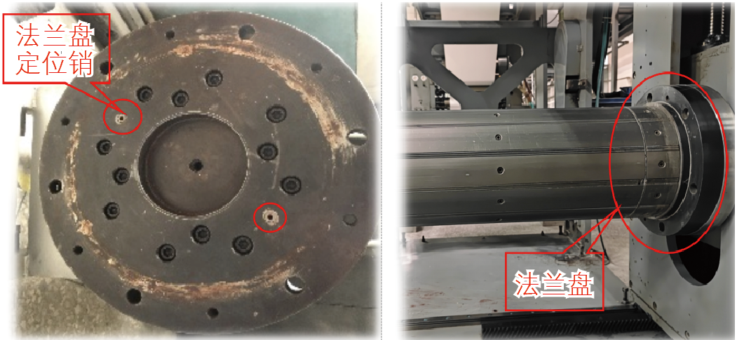 Figure 3 Flange Structure Diagram
02 / Difficulty of Installing the Expansion Shaft
Installing the expansion shaft (Figure 4) requires ensuring two things at the same time: first, the circular boss on the base flange precisely fits into the circular recess on the expansion shaft flange for proper positioning; second, the threaded holes on the base flange precisely align with the threaded holes on the expansion shaft flange. Only when both conditions are met can the installation of the expansion shaft be completed. However, previously, the company relied on the hydraulic car and the lifting function of the decoiler mechanism to achieve the alignment of the flange boss and recess for the expansion shaft, while the precise alignment of the threaded holes was entirely done manually by rotating the expansion shaft. This method has low positioning accuracy and often requires multiple attempts to achieve precise alignment of the expansion shaft.
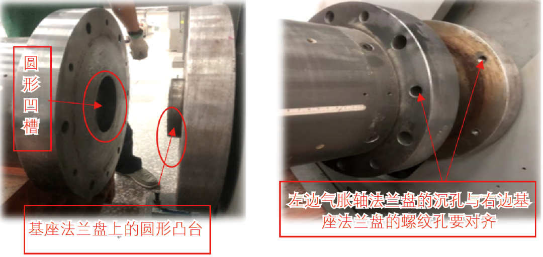 Figure 4 Installation of the expansion shaft
Installation design requirements and ideas
01/ Design requirements
To improve the maintenance efficiency of the expansion shaft and reduce the workload and difficulty of maintenance personnel, the following requirements are proposed:
(1) It can effectively reduce the maintenance time for the air expansion shaft of the uncoiling mechanism.
(2) The device is mobile, capable of precise lifting and lowering, and can flexibly rotate the air expansion shaft.
(3) Equipped with a dedicated clamp for flanges, which can accommodate various flange sizes.
(4) No interference with equipment and no negative impact on equipment.
02 / Design Concept
Design and manufacture a detachable gas expansion shaft installation and disassembly device, consisting of three main components: the mobile maintenance platform, the flange clamp installation and removal trolley, and the rapid positioning device.
Positioning and support are performed through the support wheels, and the air expansion shaft can be rotated on the support wheel, making it easy to replace the expansion strips at various angles. When installing the air expansion shaft, the threaded holes can be quickly positioned by rotating the shaft at fixed points, and precise lifting can be achieved by changing the spacing of the four support wheels. The specific implementation is as follows:
a. A total of 4 support wheels are designed, divided into 2 groups, used to support the gas expansion shaft, allowing it to rotate along the axis line, making it convenient to remove any gas expansion strip and quickly position threaded holes by rotating the shaft at fixed points when installing the air expansion shaft;
b. Using trapezoidal lead screws, bevel gears, and linear guide rail pairs, the two sets of support wheels can move symmetrically along the Y-axis, enabling fine adjustment of the air expansion shaft up and down (although the uncoiling mechanism can independently adjust the air expansion shaft up and down, it is difficult to control the adjustment amplitude and cannot be precisely fine-tuned);
c. Using gear racks and linear guide rail pairs to achieve X-axis movement of a set of support wheels, this function mainly avoids the protruding structure on the gas expansion shaft;
d. Install two directional wheels and two universal wheels at the bottom of the maintenance platform, and use Solidworks software to draw assembly diagrams of the mobile maintenance platform based on the above specific ideas.
(2) Flange clamp for installing and disassembling the trolley
Using a clamping device to clamp the flange ensures its height remains unchanged. When installing the flange, a quick-positioning device ensures the flange's position matches that during disassembly, making installation very convenient. The specific implementation is as follows:
a. Modeling the clamping structure of bench vises, and using the principle of determining a circle at three points, three clamping mechanisms are made to achieve the clamping function of the flange;
b. Using a threaded fastening mechanism and slider to move the flange plate clamp in the Y-axis direction, adjusting the distance along the Y-axis to accommodate flange plates of different diameters;
c. Using trapezoidal lead screws, bevel gears, and linear guide rail pairs to enable Z-axis movement of the flange plate fixture, it can accommodate flange plates of different diameters and adjust the vertical height of the flange plate;
d. Using a trapezoidal lead screw and linear guide rail pair to enable X-axis movement of the flange plate fixture, thereby achieving separation between the flange plate and the gas expansion shaft;
e. Two directional wheels and two universal wheels are installed at the bottom of the flange clamp fixture, and based on the above specific ideas, use SolidWorks software to draw the assembly diagram of the flange clamp assembly trolley for installation.
(3) Rapid positioning device
Using a pair of tapered cylindrical heads and circular grooves, rapid positioning of the mobile maintenance platform and flange clamp installation and disassembly trolley is achieved. The shaft front end of this device is designed as a cone to serve as a guiding mechanism. Using gravity blocks to position both vehicles simultaneously completes gravity self-locking, preventing the maintenance platform and flange fixture disassembly and disassembly of the trolley during installation and removal of the flange plate. Based on the above specific ideas, SolidWorks software was used to draw the assembly diagram of the rapid positioning device (as shown in Figure 5).
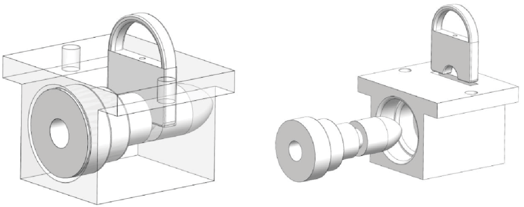 Figure 5: SolidWorks Assembly of the Quick Positioning Device
Maintenance Effect Verification
To verify the maintenance effect of the gravure press expansion shaft installation and removal device (Figure 6), technicians surveyed and collected data on the average time to repair expansion shafts using the device. They found that the average time to repair the unwind mechanism's expansion shaft decreased from 91.66 minutes to 39.91 minutes. Calculations show that using the device to repair the expansion shaft improved efficiency by 129.67%.
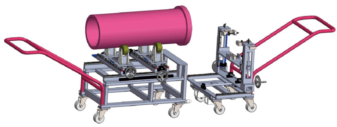 Figure 6 Simulation Diagram of the Installation and Removal Device for the Air-Expanding Shaft
The development of the installation and removal device for the gravure press air-expanding shaft reduces downtime caused by maintenance, lowers the labor intensity for operators, eliminates the need for extensive preparations to restart the machine, and significantly improves the press's effective operating rate and output quality. It also reduces the workload for maintenance staff and boosts the efficiency of air-expanding shaft repairs. Additionally, maintenance personnel can use this device to handle and repair other gravure press components like the printing rollers, cooling rollers, and traction rollers, making the machine more versatile.