


Embossing and die-cutting in one go, this new approach is efficient and cost-saving!
In response to the national call for energy saving and emission reduction, and to help achieve the ambitious goals of carbon peaking and carbon neutrality while minimizing the company's production costs, we've combined the embossing and die-cutting processes into a single step.
In the conventional production process, you first need to install the embossing plate on a large honeycomb board for the embossing step, securing it with locking screws as shown in Figure 1. The locking screws not only hold the embossing plate in place but also allow flexible adjustment of the plate's position with a special wrench, depending on the screw type. After that, the die-cutting step is done using a die-cutting plate. This method makes it easy to adjust the embossing plate's position, but since it requires two separate steps, it results in higher production costs.
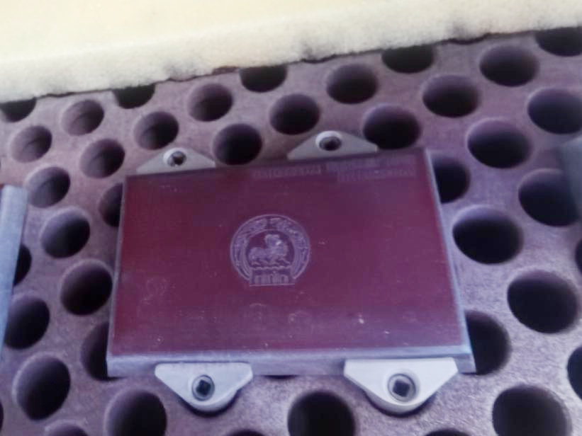
Figure 1: Illustration of Large Honeycomb Panel Installation
To reduce costs, some processes install the embossed plate directly onto the die-cutting plate using screws, merging the embossing and die-cutting steps. However, this approach has obvious drawbacks-the position of the embossed plate is hard to fine-tune, which in turn lowers production efficiency. So, how can we solve this problem?
After careful study, we found a very simple and practical method: first install the embossed plate on a miniature honeycomb panel with a scale, and then install this miniature panel onto the die-cutting plate. This solves the problem perfectly.
Function of the Holes in the Miniature Honeycomb Panel
For large honeycomb panels, each hole is the same in size and function. But for this special miniature honeycomb panel with a scale, the holes vary in size and function, as shown in Figure 2. At the same time, the positions on the miniature panel that correspond to the embossed plate also need to be punched (see Figure 3). Each miniature honeycomb panel has 14 holes in total, covering four different functions (Figure 4).
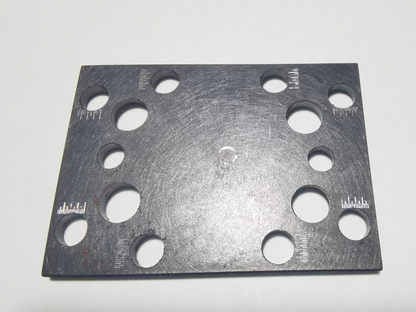
Figure 2 Mini Honeycomb Panel
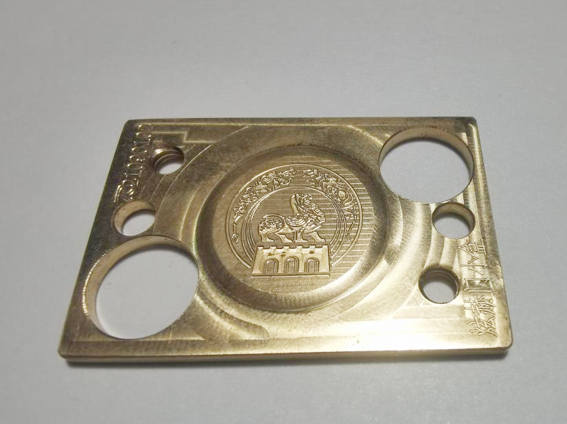
Figure 3 Embossed and Debossed Plate
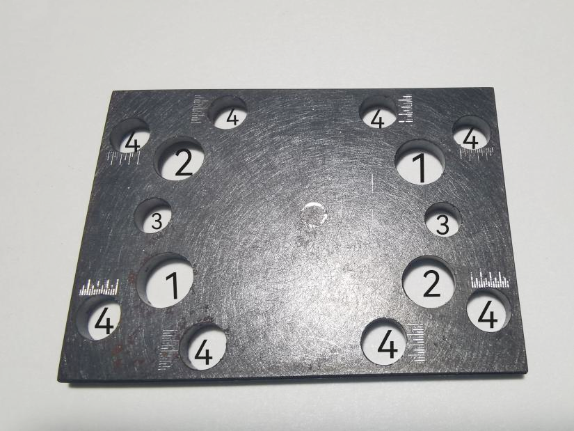
Figure 4 14 Holes in the Micro Honeycomb Board
01/ Honeycomb Board Mounting Holes (2)
Purpose: To secure the micro honeycomb board onto the die-cutting mold.
02/ Embossing Plate Mounting Holes (2)
Purpose: To fix the embossing plate onto the micro honeycomb board.
03/ Theoretical Positioning Holes (2)
Purpose: Used for the first installation of the micro honeycomb board with the embossing plate. During installation, insert the positioning pin into the theoretical positioning hole to align the top and bottom positioning holes. The theoretical positioning holes on the honeycomb board should be the same size as those on the embossing plate. Ideally, once the positioning pin is inserted, the embossing plate position should not need further fine-tuning.
04/ Embossing Plate Fine-Tuning Holes (8)
These holes are only made on the micro honeycomb board for fine-tuning; the embossing plate does not need them. Each side of the micro honeycomb board has 2 fine-tuning holes, totaling 8. The edges of the embossing plate must rest in the middle of these holes. The fine-tuning holes allow precise adjustment of the embossing plate position based on actual deviation. While in an ideal situation no fine-tuning would be necessary, in real production, paper is likely to shrink or deform due to factors like tension and humidity, so fine-tuning is required.
To provide enough space for adjusting the embossing plate, pay special attention to these two points:
(1) Point One (as shown in Figure 5): From the edge of the screw fixing the micro honeycomb board to the edge of the corresponding concentric hole on the embossing plate, leave a 1mm adjustment gap.
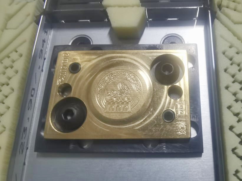
Figure 5 Front view after fixing
(2) Key point two (as shown in Figure 6): On the back of the miniature honeycomb panel, leave a 1mm adjustment gap from the edge of the screw that fixes the embossed plate to the edge of the corresponding concentric hole in the miniature honeycomb panel.
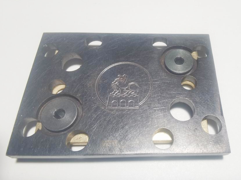
Figure 6 Fixed Backside Situation
Steps for Precisely Adjusting the Embossed Plate Position
(1) Loosen the screws that fix the embossed plate, as shown in Figure 7;
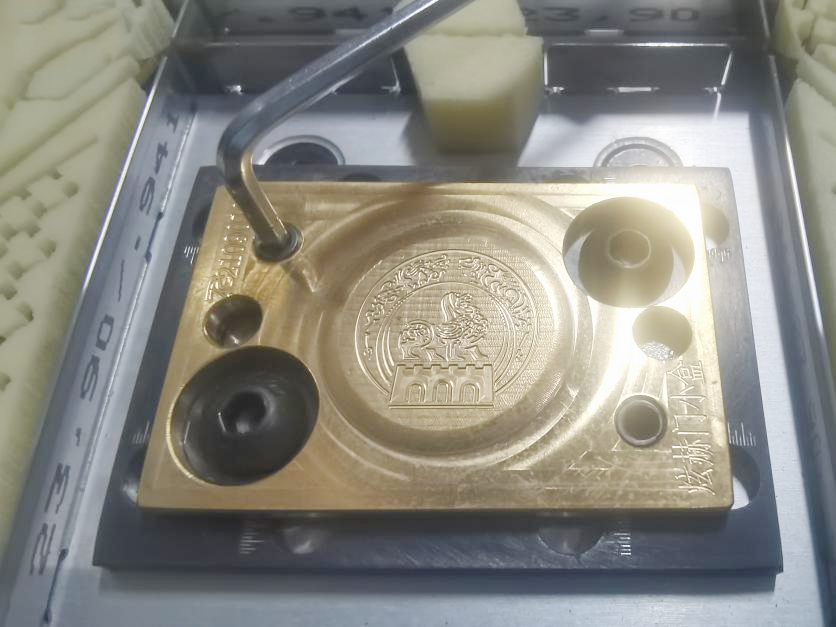
Figure 7 Loosen the bumps-and-grooves plate fixing screws
(2) Insert a small pry bar into the adjustment hole of the bumps-and-grooves plate (the diameter of the small pry bar must be smaller than the diameter of the adjustment hole), and adjust the direction of the offset according to the bumps-and-grooves displacement, as shown in Figure 8;
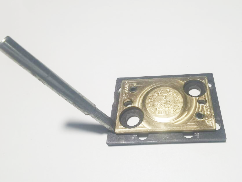
Figure 8 Adjusting the Offset Direction
(3) Carve a ruler along the edge of each side of the miniature honeycomb panel. The edge of the embossed plate must press at the midpoint of the ruler, and the ruler should also be positioned near each fine-tuning hole. Carve 2 rulers on each side, totaling 8. Adjust the offset amount according to the embossing offset situation, as shown in Figure 9;
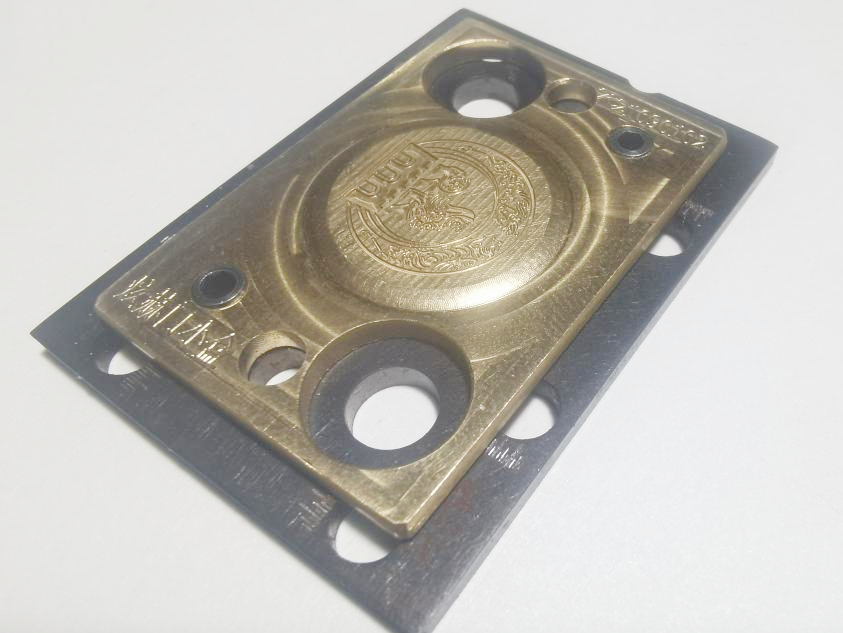
Figure 9 Adjust the offset
(4) Once adjusted, tighten the screws that fix the male and female plates.