
An 11-year-old gravure printing line frequently experiences registration system failures - how can one fix it once and for all?
The company I work for has a Cerutti R960 ten-color gravure printing line, which has been in operation for about 11 years. The line is equipped with an Automec registration system, and after years of use, this system often causes machine stoppages due to communication errors during startup and production. These issues not only increase printing waste but also affect product quality. In this article, I analyze the causes of communication failures in the registration system and summarize some relevant solutions.
Principle of Registration System Communication
The communication diagram of our Automec registration system is shown in Figure 1. It uses a fully integrated control platform provided by Germany's Beckhoff, combining a PC and EtherCAT. The PC is a Beckhoff industrial computer C6920-0050, and EtherCAT integrates all automation components, including IP67-rated EtherCAT I/O, EtherCAT automation software, and servo drives, serving as the fieldbus for the entire system. Communication between the PC and EtherCAT I/O is achieved through the EK1100 coupler, connecting the EtherCAT network with the EtherCAT I/O terminals to control all operational functions, including the movement of printing color units, data recording, operation, and remote monitoring. The system communication is based on EtherCAT ring topology, providing line redundancy to ensure normal operation even in the event of a disconnection.
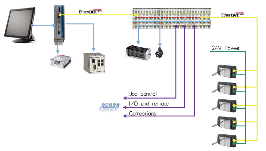
Figure 1 Color Matching System Communication Overview
This design ensures quick setup, requiring only a few low-voltage cables to be connected during configuration. All system monitoring tasks are handled by the TwinCAT HMI tool, with no need for drivers or other communication protocols. Within the TwinCAT HMI tool, variables are treated as program logic within the same software.
Fault Analysis of Color Matching System Communication Issues
The Oteme color matching system uses a Beckhoff PC communicating with EtherCAT I/O via CAT5 (standard Category 5 Ethernet cable) in standard 100BASE-TX mode. Following the EtherCAT bus coupler EK1100 are 59 EtherCAT terminals and a bus end terminal in series. The EK1100 bus coupler converts Ethernet 100BaseTX telegrams into E-bus signals for transmission between EtherCAT terminal modules. Essentially, E-bus is EtherCAT, except the transmission uses spring clip contacts on the backplane instead of network cables. The concept of "one network to the end" means each I/O module serves as an EtherCAT slave. Each EtherCAT slave device has four EtherCAT communication ports: Port0 (A), Port1 (B), Port2 (C), and Port3 (D).
However, the Oteme set-point system module slaves only have two communication ports, and the signal flow through the modules from left to right is shown in Figure 2. When an EtherCAT frame passes through a slave, it enters the module via Port0 (A), then goes through the EtherCAT Processing Unit, and leaves the slave module through Port1 (B). If there is a communication issue during the process, the preceding EtherCAT module of the faulty module will automatically lock its Port1, causing the EtherCAT telegram to return.
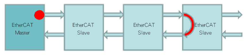
Figure 2: EtherCAT Message Return When Communication Fails
Each EtherCAT I/O module has six spring contacts. Since the modules are connected in series, they communicate with each other via the E-bus on these six contacts. Eventually, the data is transmitted through the contacts of each module to the coupler. In the current system, there is one coupler module with 60 I/O modules connected in series downstream. Due to module aging, the contact resistance becomes too high or the input signal voltage is too low, resulting in insufficient input current to drive the PLC's input interface circuit, which causes communication failures.
Troubleshooting Communication Issues in the Color Registration System
(1) When a communication failure occurs, the signal returns from the previous module, and the EtherCAT diagnostic system will indicate the module where the fault starts. Sometimes, unplugging and re-plugging the faulty module, cleaning the contacts of the module to remove oxidation, or replacing the module can temporarily restore communication. However, this is just a temporary fix, and communication issues may occur again after some time.
(2) Restructuring the existing I/O modules involves changing the original 1-master-1-slave communication setup to a 1-master-4-slave setup (see Figure 3). This includes adding three more EK1100 couplers, replacing the previous three power modules EL9001 in the PLC with coupler EK1100 modules that have built-in power, and connecting the four couplers in series. Each coupler handles 15 I/O modules, which significantly shortens the signal return path for the downstream modules, improves communication reliability between modules, and increases data redundancy. This method was tested in our color registration system renovation, and for nearly a year, there have been no communication failures in the system.
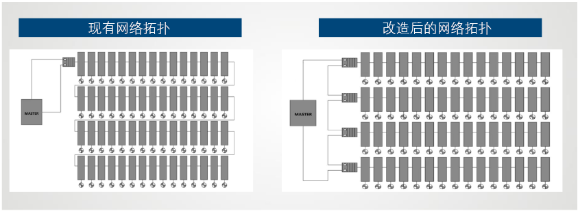
Figure 3 Current Network Topology and Upgraded Network Topology
This article studies and analyzes the communication principles of the Oerlikon color registration system, investigates the causes of communication failures in the system, and summarizes the solutions. In the end, the communication issues of the color registration system were resolved, reducing production impacts caused by communication problems in the equipment's color registration system, and greatly improving equipment efficiency. Peers with similar equipment can refer to this approach.